Saturday, February 3, 2018

Fin de saison 2017 / End of the season 2017

Après etre resté au quai 2 grosses semaines de temps, j'ai fait resortir mon bateau de l'eau et l'ai fait remettre dans le fond de la cour. On était a la mi septembre et j'avais fait pas mal tout ce que je voulais faire cette année. J'ai fait quelques bricoles puis j'ai procédé a l'hiverisation de mon bateau. Ce qui consiste a envoyer de l'antigel a plomberie dans toute la tuyauterie alimentant les robinets de la cuisine et de la toilette a l'avant. Et aussi dans l'échangeur de chaleur du moteur. Puis j'ai commencé a assembler encore une fois, une charpente pour supporter une bache au dessus de mon bateau. J'utilise aussi ce plastique blanc parfois reconnu sous le nom de "coroplast", autour du mat et des bas-haubans. D'une année a l'autre, ma charpente n'est jamais tout a fait identique. Parfois plus basse, parfois plus haute, parfois plus arrondie a l'avant. Ma paresse joue bien compréhensiblement un grand role. Je me suis rappelé que l'hiver passé, j'ai pas tellement aimé la performance de la charpente que j'avais bati alors, trop minimaliste, pas assez pointue, qui laissait des grands espaces ou la neige pouvait s'accumuler sur le dessus du bateau. Donc cette année, je me suis davantage forcé et bati une charpente qui fera un meilleur travail. Et a mi-chemin dans l'hiver, je peux dire que jusqu'a date, j'en suis satisfait.
------------------------------------------------------------------------------------
After having spent 2 long weeks at the pier, I asked for my boat to be taken out of the water and back in the bottom of the yard. It was the middle of september and I have done pretty much everything I planned to do this year.  After doing some touch-ups here and there, I performed the hivernisation procedure which consist in pouring plumbing antifreeze in all tubings going to the faucets in the kitchen and in the toilet. And also in the engine heat exchanger. Then I started to build, once again, a framework over the boat, that will support a tarp. Over some areas, I also use this white plastic sheet sometimes called "coroplast", mostly around the mast and inner stays. From one year to the next, my framework is never exactly the same. Sometimes lower, sometimes higher, sometimes with a more rounded end toward the front. Very understandably, my laziness plays a big role. I remembered that last winter, I was not happy about the performance of the framework I built then. It was too minimalist, not pointy enough, and left many areas accumulate lots of snow on the top of the boat. So this year, I made more effort and built a framework that will do a better job. And so far, midway through the winter, I can say I am satisfied with it.


Mise a l'eau été 2017 / Launching summer 2017

Arrivé a la fin aout 2017, il me restait encore beaucoup de cablage a faire, et poser les panneaux de disjoncteurs. Mais la partie puissance était terminée. Le système d'alimentation en carburant pour le moteur était en place tout comme le panneau des instruments du moteur. Je pouvais donc le démarrer a la pression d'un bouton. Et l'arreter en basculant un interrupteur. Alors j'ai dit "au diable le cablage qui reste a faire!! Je le met a l'eau et je finirai le travail tout en étant au quai!" Cette année-ci, pour la première fois, mon bateau a avancé sous son propre pouvoir, ce qui est pour moi une étape significative. Et puis, travailler a compléter le cablage, dans mon bateau, tout en le sentant bouger sous mes pieds, ca n'a pas de prix!
------------------------------------------------------------------------------------
Arrived at the end of august 2017, there was still a lot of wiring to be done and breakers panels to install. However, the power section was done. The fuel system was installed as well as the engine instrument panel. I could start it by pressing a button and turn it off by flipping a switch. So I said "the hell with the remaining wiring. I'll launch it now and finish the job while at the pier!" That year, for the first time, my boat made way under its own power, which is for me a significant milestone. Besides, completing the wiring job while feeling my boat move under me feet, is priceless!


Friday, February 2, 2018

Travaux été 2017 / Work done in summer 2017

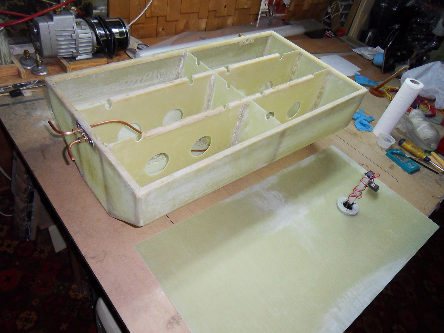
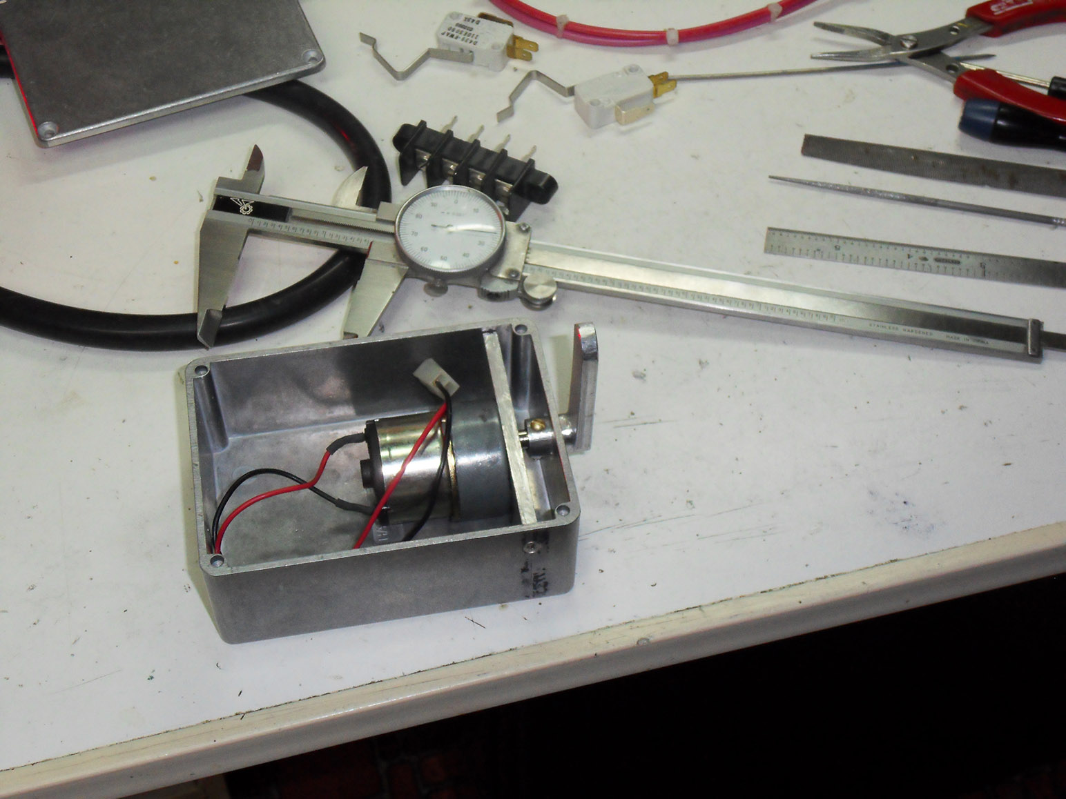
L'été 2017 a essentiellement été consacré a installer le matériel que j'avais fabriqué durant l'hiver dernier. Il y a eu mon petit servomoteur d'arret pour le moteur, que j'ai monté sous une grosse équerre servant a maintenir en place le cable téléflex du controle des gaz du moteur. Ca a été un gros soulagement pour moi de constater que mon réservoir de diesel entrait a la perfection sous le plancher dans la cabine. Je l'ai solidement fixé en place avec des bouts de chene blanc. Ce réservoir ne doit pas bouger meme en cas de gite sévere ou pire.  J'ai completement refait mon frigidaire avec ma nouvelle cuve en fibre de verre, pour faire en sorte qu'il soit plus aisé a démonter, ce qui peut arriver pour toutes sortes de raisons. A présent un peu plus court, ca me permet de mieux l'isoler aux extrémités. Les faces avant et arrière sont isolées avec des panneaux sous vide hyper performants mais les cotés, le dessus et le dessous le sont avec des panneaux de mousse conventionnels.

J'ai logé le module de compresseur / condenseur du frigidaire dans le fond de la cale. C'est sans doute l'endroit le plus frais dans tout le bateau. Mais c'est aussi un endroit risqué en cas d'avarie et voie d'eau. Donc j'ai placé ce module a l'intérieur d'un boitier dont le fond est étanche, qui est lui fixé au fond de la cale. Ce boitier est suffisament large pour permettre une bonne circulation d'air tout autour du compresseur et du condenseur. Dans la meme section de cale sous le plancher, j'ai mis la batterie de démarrage et une grosse barre réunissant tous les négatifs de la batterie en un point.

J'ai complété l'installation du réservoir de carburant, un robinet, toute la tuyauterie incluant un bulbe pour amorcer le circuit ainsi qu'un filtre primaire et séparateur d'eau de bonne capacité. J'ai ensuite posé la base du circuit électrique, en commencant par la section puissance. Donc, tout les gros fils, partant de la batterie de démarrage et de l'emplacement des deux batteries de servitude a venir, les sélecteurs pour démarrer le moteur en se servant soit de la batterie de démarrage ou bien de l'une ou l'autre ou les deux batteries de servitude.

Finalement, j'ai fait tout le filage de tous les appareils électriques a bord. Feux de position, la radio VHF, le fridge, l'éclairage cabine, le guindeau, ect. Tous les fils sont ammenés jusqu'au point ou je planifiais de poser le panneaux de disjoncteurs. Tout ce filage tient évidemment en compte le courant anticipé pour chaque appareil. Le guindeau nécéssite du fil #4. Le fridge, du #14. Pour les circuits relatifs a l'éclairage, tout fait avec des LEDs, du numéro #18 convient amplement. Il y a aussi un circuit de 120 VAC pour lorsque je suis a quai. Ce circuit a son panneau de disjoncteurs dédié. J'ai acheté tout fait ce panneau de disjoncteurs pour le circuit du 120 VAC. Mais un second petit panneau comprenant le disjoncteur du guindeau et indicateur du niveau de fuel dans le réservoir, ainsi que le panneau de disjoncteurs de tous les circuits 12 Volts a bord, je les ai faits moi-meme. Une fois installé, c'est pas mal dutout.
------------------------------------------------------------------------------------
The summer 2017 was mostly spent installing the stuff I made in the last winter. There was my small engine shutoff servomotor  that I located under a large square that holds the throttle teleflex cable. It has been a big relief for me to find out my fuel tank was fitting perfectly under the cabin floor. I strongly fixed it in place with pieces of white oak. That tank must not move even in severe listing or worse. I have completely redone my refrigerator with my new fiberglass tank, to make it easier to take apart, which can happen for many good reasons. Now a bit shorter, I can better insulate it at both ends. The front and rear faces are insulated with high-performance vacuum insulated panels but both sides as well as the bottom and the top are done with ordinary foam panels.

I fixed the refrigerator compressor and condenser module in the bilge. Its without any doubts the coolest spot in the boat. But its also risky in case of water leak. So I placed that module in a box with a watertight bottom which is fixed in the bottom of the bilge. That box is large enough to allow a good air flow around the compressor and the condenser. In the same bilge section, I installed the starter battery and a big bussbar on which all the battery negatives are united in one spot.

I completed the installation of the fuel system, with a small shutoff valve, all the plumbing, including a priming bulb, and a large primary filter and water separator. Then I installed the foundation of the electrical system, starting with the power section. So all the heavy gauge wires leaving the starter battery and the two house batteries to come, the power selectors to start the engine either with the starter battery or one or the other or both house batteries.

Finally I have done all the wiring for all onboard electrical appliances. Navigation lights, the VHF radio, the refrigerator,  cabin lighting, anchor winlass, ect. All the wires are routed up to the point I was planning to install the breaker panel. All the wiring is done in consideration with the expected current for each of them. The winlass requires gauge #4. The refrigerator, gauge #14. For all the circuits relevant to lighting, all done with LEDs, gauge #18 is sufficient. There is also a 120 VAC circuit for shore power. That circuit has a dedicated breaker panel. I have bought an already made breaker panel for the 120 VAC circuit. But I made myself the small breaker panel for the winlass, fuel level indicator, and the main breaker panel for all the onboard 12 V circuits. Once the installation done, it looks quite good.


Thursday, February 1, 2018

Pilote automatique / Autopilot

J'ai un pilote automatique de barre franche Raymarine ST4000+ qui était installé dans mon bateau a l'achat en 2004. Ce ST4000+ n'est pas mauvais en soi et pourrait encore très bien faire le travail. Cependant mon bateau est maintenant équippé d'une barre a roue. Le module électronique du ST4000+ peut facilement etre reconfiguré pour actionner une barre a roue.  Il me reste qu'a trouver le mécanisme qui actionne la roue. J'avais la possibilité d'en acheter un neuf, et c'est pas donné. Ou bien de m'en fabriquer un, a mon gout. J'ai écouté les gens faire des commentaires au sujet des pilotes automatiques. Il y a toujours le problème de la maudite courroie qui casse, ce qui arrive toujours dans le pire moment. Et qui est difficile a remplacer. De plus, ces pilotes automatiques sont des gros consommateurs d'électricité.

J'analyse les problèmes soulevés. Il faut éliminer la courroie. Et réduire la consommation électrique. Cette consommation est exacerbée par la friction dans le mécanisme du gouvernail. Mais le mien est extremement tendre et largement compensé. Donc, peu de friction énergivore a ce stade. Il reste la friction a l'intérieur-meme du mécanisme d'entrainement. Ayant pu mettre la main sur un vieux pilote automatique de barre a roue, je constate que la courroie, une fois tendue pour entrainer la roue, applique une pression significative sur l'arbre du moteur et cette pression fait que le moteur consomme beaucoup plus de courant que nécéssaire. Mais si j'élimine cette courroie pour remplacer le mécanisme d'entrainement par quelque chose qui n'offre aucune friction, je suis doublement gagnant.

Je me suis fait  un plan. Puis fait tailler au laser, des pièces en alliage d'aluminium. Et ensuite je les ai assemblé. D'abord une cage dans laquelle se trouve six roulements a billes en inox. Puis une couronne extérieure qui vient embarquer sur les roulements a billes de la cage. Et une fois cette couronne assemblée, elle ne peut plus débarquer car les roulements a billes se trouvent a rouler a l'intérieur d'une voie en U formée des trois piecces constituant la couronne. Je me retrouve donc avec le mécanisme central de l'entrainement de la barre a roue. Sur la couronne extérieure, sur un diamètre de 13.369 pouces précisément, donnant une circonférence de 42 pouces, se retrouve 168 vis machine #6-32 a tous les quarts de pouce, formant les dents d'une grande engrenage. Le moteur électrique entraine une première engrenage puis une seconde fixée a une roue dentelée qui, par le biais d'un levier de commande, vient s'engager ou se désengager sur ma grande engrenage-couronne.

Le restant est un boitier fabriqué en fibre de verre. En dernier, toutes les pièces en alliage d'aluminium sont traitées avec un appret au polymère vinylique pour les protéger contre la corrosion. L'intérieur de la voie la ou les roulements a billes roulent recoit une mince couche de graise Marelube.
------------------------------------------------------------------------------------
I have a Raymarine ST4000+ tiller autopilot which was installed in my boat at purchase time. That ST4000+ is not bad by itself and could still do the job. However, my boat is now equipped with a wheel helm. The ST4000+ electronic module can easily be reconfigured to actuate a wheel. The only thing left is to find a suitable drive. I had the possibility to buy such drive, and its quite expensive. Or building one, to my liking. I listened to people making comments about autopilots. There is always that damn strap that breaks at the worst time and is difficult to find a replacement. Furthermore, autopilots needs lots of electrical power.

I analyze these problems. The strap must go. And find a way to reduce electrical consumption. That consumption is made worse by the friction in the rudder mechanism. But mine is very tender and highly compensated. So there is very little electrical-consumption-induced friction at this point. What is left is the friction inside the drive unit itself. Having been able to put my hand on an old autopilot drive unit, I observed that when the strap was taut to engage the drive, was excerting a strong pressure on the motor shaft and that pressure caused the motor to pull lots more current than necessary. But if I eliminate the strap to replace the drive mechanism with something else that offers no friction at all, it will be a win -win situation.

I made myself a plan. Then made all the needed pieces laser-cut from an aluminum alloy. Then assembled them. First a cage in which are mounted 6 stainless steel bearings. Then an outer ring that fits over the cage with the bearings. Once that ring assembled, it can no longer come off as the bearings rolls inside a U shaped track made of the three pieces forming the outer ring. Thus I get the main part of the autopilot drive. On the outer ring, over a diameter of 13.369 inches, giving a circumference of precisely 42 inches, are 168 #6-32 machine screws, spaced 1/4" apart, forming the teeth of a large ring gear. The electric motor drives a first gear then a second on which is attached a sprocket which, moved by a lever, can mesh in or out of the large ring gear.

The rest is a body made of fiberglass. At last, all the aluminum pieces were treated with a polyvinylic primer for corrosion prevention. The inside of the track where the bearings rolls, received a thin coat of Marelube grease.


Travaux pour l'hiver 2017 / Winter 2017 projects

Motivé par les succès de la seconde mise a l'eau ainsi que par les encouragements de personnes qui ont assisté a mes essais, j'ai continué a travailler pendant l'hiver 2016-2017 pour prendre le plus d'avance possible en vue de la saison suivante, de l'été 2017. Au programme, fabriquer un réservoir de diesel conforme au fond de la cale et d'une capacité de 100 litres. A l'aide d'une résine époxy approuvée a cet usage.  Aussi, des moustiquaires pour aller sous mes petits hublots situés au dessus des couchettes. Refaire ma cuve de frigidaire, en fibre de verre, quelques pouces plus petite que la cuve actuelle en inox. Fabriquer un mécanisme qui va piloter la pompe a injection du moteur. Normalement, les moteurs diesels modernes ont un solénoide d'arret, muni d'un plongeur relié au mécanisme de la pompe a injection. Quand l'interrupteur du moteur est en position "marche", ce solénoide est alimenté. Le plongeur est attiré vers le coeur du solénoide et par une bielle relié a une valve, la carburant dans la pompe a injection peut circuler. Mais quand on met l'interrupteur en position "arret", le plongeur est relaché et reprend sa position de repos via un ressort de rappel. la bielle qui le relie au mécanisme interne de la pompe a injection vient interrompre la circulation du carburant et le moteur arrete. Mais mon moteur n'a pas de tel solénoide. La seule facon de l'arreter est en actionnant un levier sur le coté de la pompe a injection. Il y a un trou bouché par une grosse noix, sur le coté de la pompe, la ou normalement ce solénoide devrait etre fixé mais rien ne me dit que si j'achète un solénoide et le pose en place, cela va fonctionner. Donc je me suis fabriqué un petit servomécanisme a partir d'un moteur électrique, de micro interrupteurs et quelques composants électroniques, le tout bien proprement monté dans un petit boitier métallique. J'ai fabriqué un second panneau de commande pour mon moteur. Dans le passé, j'en avais fabriqué un premier dans lequel j'avais incorporé un module électronique affichant des paramètres électriques. Ultimement, j'ai changé d'avis et j'ai décidé que ces paramètres électriques allaient etre affichés d'une autre facon. J'ai donc refait mon panneau moteur. J'ai également fabriqué mes feux de navigation, avec des leds.
------------------------------------------------------------------------------------
Motivated by the success of the second launch as well as by people who witnessed my tests, I kept working during the winter 2016-2017 to have as much stuff ready to be installed in the next season, summer 2017. On the program, building a fuel tank that would closely fit in the bottom of the bilge, with a capacity of 100 liters. With an epoxy resin which has been approved for that use. Also, building slidable mosquitoe nets that would go right under the small hatches over the beds. Redo the refrigerator tank out of fiberglass, a bit smaller than the one made of stainless steel. Building an actuator that will drive the engine injection pump. Normally, modern diesel engines are equipped with a shutoff solenoid, built with a movable core linked to the inner mechanism of the injection pump. When the engine switch is in the "run" position, the solenoid is powered. The core is pulled in and its linkage is commanding a valve in the injection pump to let the fuel flow. Then when the switch is put in the off position, the core returns in its rest position with a spring. The linkage attaching the core to the valve shuts the fuel flow and the engine stops. But my engine does not have such shutoff solenoid. The only way to turn it off is by pulling on a small lever on the side of the injection pump. There is a hole plugged with a large screw, on the side of the pump, where a shutoff solenoid is normally screwed on, but nothing tells me if I buy that solenoid and I install it, its going to work. So I built a small two position servomotor, with an electric gearmotor, a few microswitches and electronic parts, everything cleanly fixed inside a small metal cabinet. I built a second engine instrument panel. In the past, I already built one, in which I fixed an electrical data display module. Since then I changed my mind and figured the electrical data display will be displayed somewhere else. So I redone my engine instruments panel. I also build my own LEDs navigation lights.